Explanation
by Toon Van Hoecke at the Universiteit Gent
This applet can be used to build and
analyze DC and AC electrical circuits.
When the applet is loaded a default
circuit is build. It is extracted from a text file that
can be found at "lists/default.txt" in
the directory containing the jar files. To load another
build file, type its name and press the "Load"
button. To open a new window with the list of loadable
text files, click here. If you want to see a text list of the elements
currently on the screen, press the "List"
button.
If you want to change the
size of the circuit grid, change the number of rows and
columns and then press the "Set grid" button. Be aware that all
components on the screen will disappear.
The "Show ->" button is used to visualize
arrows representing the chosen current direction.
New components for the
circuit are entered by a "drag and drop" method. Press the button of
the component you want to add, hold the mouse button and
release it on the position where you want to put this
component. Any horizontal or vertical position between
two black dots can be taken.
The following direction
independent components can be added:
 Resistor: its value (in Ohm) can be
entered next to the resistor button.
Resistor: its value (in Ohm) can be
entered next to the resistor button. Capacitor: value entered in Farad.
 Inductor: value entered in Henry.
 Light bulb: characterised by voltage
(in V) and power (in W). The color varies from
black (no current) to white (maximum
current).
Light bulb: characterised by voltage
(in V) and power (in W). The color varies from
black (no current) to white (maximum
current).  Wire: used to close
connections.
Wire: used to close
connections. Switch: can be opened and closed.
Some components need are
polarised and thus have a positive and a negative side.
The direction can be set by choosing "+ down/right" or "+ up/left" of the "Direction" list item. The following
direction dependent components can be added:
 Battery: value entered in V.
 General
Voltage source:
its function prescription (in V) can be entered
next to the source button and it default value is
"sin(t*2*pi*f)". Use "t" as
time variable, "f" as frequency
variable and "p" as period variable.
The frequency can be entered in the text field
below.
General
Voltage source:
its function prescription (in V) can be entered
next to the source button and it default value is
"sin(t*2*pi*f)". Use "t" as
time variable, "f" as frequency
variable and "p" as period variable.
The frequency can be entered in the text field
below. Current
Source: value
entered in A.
Current
Source: value
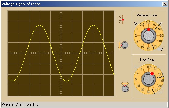
entered in A. Oscilloscope: simulation of a
one-beam-oscilloscope. A window with the view on
the particular oscilloscope can be opened by
selecting the "Display Oscilloscope"
option of the popup menu when you click the right
mouse button on the oscilloscope icon in the
circuit.
Oscilloscope: simulation of a
one-beam-oscilloscope. A window with the view on
the particular oscilloscope can be opened by
selecting the "Display Oscilloscope"
option of the popup menu when you click the right
mouse button on the oscilloscope icon in the
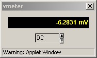
circuit. Voltmeter: simulation of a digital
voltmeter. Use the "Display Voltmeter"
option of the right-mouse-button popup menu.
Voltmeter: simulation of a digital
voltmeter. Use the "Display Voltmeter"
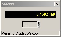
option of the right-mouse-button popup menu. Ampèremeter: simulation of a digital
ampèremeter. Use the "Display
Ampèremeter" option of the
right-mouse-button popup menu.
Ampèremeter: simulation of a digital
ampèremeter. Use the "Display
Ampèremeter" option of the
right-mouse-button popup menu.
The "Calculate" button is recalculating
data. A number of "Step #" data points is calculated iteratively
with a step size of "Step (s)". So the step size is entered in
seconds (default is 1e-6 s).
The "Start/Pause" button and the "Reset" button are used when a real
time clock is necessary. This is in situations with slow
varying sources or the displaying of voltage or current
graphs. The number of frames per second = 1 / (10 * step
size). This is real time up to step sizes of 0.01s.
You can move a component
to another position by using "drag and drop".
Other actions are available as options of the popup menu
when you click the right mouse button on the oscilloscope
icon in the circuit. The possible options are only
enabled if it is relevant:
- Delete
Component:
deletes the selected component.
- Change
Value: changes
the value or function of the selected component.
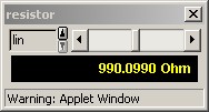
- Display
Value Knob:
pops up a little window with a scroll bar to
change the value dynamically (linear steps or
logaritmic steps).
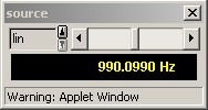
- Display
Frequency Knob:
pops up a little window with a scroll bar to
change the frequency of an ac source dynamically.
This only works when the "f" variable
is present in the function prescription.
- Show/hide
Value or Function: concerns the display on the
circuit grid.
- Set
Label: gives a
name to the selected component.
- Display
Oscilloscope:
pops up the oscilloscope window of the selected
oscilloscope.
- Display
Voltmeter:
pops up the digital voltmeter window of the
selected voltmeter. The mode can be switched
between DC and AC (rms value).
- Display
Ampèremeter:
pops up the digital ampèremeter window of the
selected ampèremeter. The mode can be switched
between DC and AC (rms value).
- Display
Voltage Graph:
pops up a voltage graph of the selected component
(use Start button).
- Display
Current Graph:
pops up a voltage graph of the selected component
(use Start button).
- Change
Switch:
changes the status of the selected switch: open
or closed.
- Change
Polarity:
switches the + and - signs of polarizable
components.